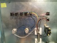
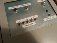
Laser Electronics: Difference between revisions
(Initial Commit) |
mNo edit summary |
||
| (7 intermediate revisions by 3 users not shown) | |||
| Line 1: | Line 1: | ||
== Laser Cutter Electronics == | == Laser Cutter Electronics V2 (not complete) == | ||
===Leadshine DM442 stepper drivers=== | |||
Requires program: [http://www.leadshine.com/UploadFile/Down/ProTuner_DM_Setup_2013-11-06.zip ProTuner DM] | |||
Requires FTDI USB to RS232 cable, plus DIY adapter: [[File:DM442_cable.jpg|100px]] | |||
Knockoff RS232 converters don't provide full RS232 voltage levels, and the DM442 drivers won't respond. | |||
Alternatively you can use an old laptop with a hardware RS232 port. | |||
After installing the software, in C:\windows\sysWOW64, in an elevated prompt, run: | |||
* regsvr32 mscomm32.ocx | |||
* regsvr32 mscommctl.ocx | |||
* regsvr32 COMDLG32.OCX | |||
* regsvr32 MSHFLXGD.OCX | |||
Note that this program writes to the DM442 immediately after making changes, so BE CAREFUL. | |||
===Internals=== | |||
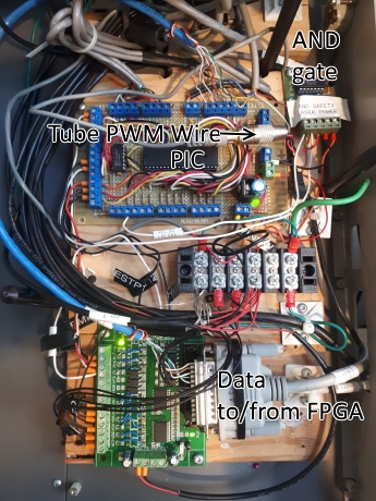
[[File:LaserInternalsV2-Front.jpg]] | |||
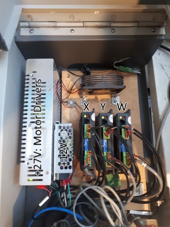
[[File:LaserInternalsV2-Back.jpg]] | |||
The X, Y, W stepper drivers (Leadshine DM442) drive the three stepper motors, and are powered with 27V. | |||
They are constant-current drivers, and are limited in software to an appropriate current for the three axes. | |||
The software configuration means that they are NOT interchangeable. Replacement units MUST be programmed (see above). | |||
The PIC board receives 12V and provides 5V for the rest of the electronics. | |||
===FPGA=== | |||
The FPGA driver is a [http://store.mesanet.com/index.php?route=product/product&product_id=55 MESA 5i25] | |||
The LinuxCNC driver is [http://www.linuxcnc.org/docs/devel/html/man/man9/hostmot2.9.html HOSTMOT2] | |||
===LinuxCNC changes=== | |||
We added custom components binaryscaler.comp and laserpwmcalc.comp | |||
binaryscaler produces a floating point [0-1] value based on the front panel switches. | |||
laswerpwmcalc handles several inputs and produces a PWM output to drive the laser tube: | |||
*graster | |||
*binaryscaler [0-1] | |||
*M3/M4 S[0-1] | |||
*actual velocity | |||
<pre>sudo halcompile --install laserpwmcalc.comp</pre> | |||
M3 is the conventional 'spindle activate' command used to turn the laser on/off. Historically it was either on or off, but now accepts fractional power. | |||
Features described below should not work in M3, otherwise referred to as 'compatibility mode'. | |||
M4 is the new 'spindle activate' command which uses the concept of severance energy. | |||
The movement speed of the laser (feed rate) is automatically coordinated with the cutting power. | |||
Corner compensation is always enabled in M4, so as the feed rate decreases the cutting power decreases to match. | |||
It is also possible (and recommended with M4) to enable adaptive feed by setting M52. | |||
E.g. for a low energy cut, the laser will operate at maximum speed, and a low power. Increasing the energy increases the cutting power to maximum. Further energy increases instead will decrease the cutting speed. | |||
Note that M4 speed changes will only *decrease* the feed rate. You should set the feed rate to the highest acceptable value. | |||
===Recommended Gcode=== | |||
<pre> | |||
G20 (Inches) | |||
M52 (Adaptive feed enable) | |||
G64 P0.001 (Path blending enable; tolerance at machine resolution, 0.001") | |||
M4 S0.5 (S value [0, 1] for severance energy) | |||
</pre> | |||
or | |||
<pre> | |||
G21 (Millimeters) | |||
M52 (Adaptive feed enable) | |||
G64 P0.0254 (Path blending enable; tolerance at machine resolution, 0.001") | |||
M4 S0.5 (S value [0, 1] for severance energy) | |||
</pre> | |||
== Laser Cutter Electronics V1 (out of date)== | |||
[[File:Laser-control_board.pdf]] | [[File:Laser-control_board.pdf]] | ||
| Line 7: | Line 84: | ||
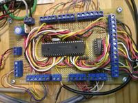
[[File:Laser_electronics.jpg|200px]] | [[File:Laser_electronics.jpg|200px]] | ||
[[File:Laser_driver.jpg|200px]] | |||
[[File:Laser_Swtch_wiring.jpg|200px]] | |||
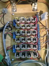
[[File:Lasor-switches.jpg|200px]] | |||
===Laser control board pinout=== | |||
Left Header: (Top to Bottom) | |||
* GND (Shield) | |||
* SW_1 (Yellow) | |||
* SW_2 ( Green) | |||
* SW_4 (Blue) | |||
* SW_8 (Lt Purple) | |||
* Disable (Lt Brown) | |||
* ... | |||
Top Header: (left to right) | |||
* Output to LEDs | |||
* PWM output to laser tube (2 pins - black, red) | |||
Bottom Header: (Left to right) | |||
* Laser EN (Black) | |||
* ... | |||
* (I/O to parallel port here) | |||
Right Header: (Top to bottom) | |||
*... | |||
* (Power Input & output to stepper driver) | |||
==== Laser Power controller board pinout ==== | |||
Long header: | |||
* yellow = switch input | |||
* blue = parallel input | |||
* green = output to PIC (where switches used to go) | |||
Top header: | |||
* Pin 1 (Orange wire) LASER_EN | |||
* Pin 3,4 - (Purple) Mode Switch | |||
* Pin 5 - Ground | |||
* Pin 6 - 5V | |||
=== Code === | === Code === | ||
When we replaced the motor controllers back in 2016; we moved the step generation logic off the PIC, and replaced it with a single "MOTOR_EN" output instead. | |||
The original code changes have not been found, so the following is assumed but unvalidated. | |||
<pre> | <pre> | ||
/* | /* | ||
* Laser Engraver Controller - ver. 1. | * Laser Engraver Controller - ver. 1.1a | ||
* | * | ||
* Written by: Andrew Kilpatrick | * Written by: Andrew Kilpatrick | ||
* Copyright: 2009 | * Copyright: 2009, 2016 | ||
* | * | ||
* Runs on PIC16F877A | * Runs on PIC16F877A | ||
| Line 23: | Line 143: | ||
* - parallel port or other type of bit-bang connection to PC | * - parallel port or other type of bit-bang connection to PC | ||
* - E-stop and system run control support (amp enable, charge pump, etc.) | * - E-stop and system run control support (amp enable, charge pump, etc.) | ||
* - controls laser PWM control | * - controls laser PWM control | ||
* | * | ||
* Hardware I/O: | * Hardware I/O: | ||
* - RA0 - laser power bit 0 | * - RA0 - laser power bit 0 - input - active high | ||
* - RA1 - laser power bit 1 | * - RA1 - laser power bit 1 - input - active high | ||
* - RA2 - laser power bit 2 | * - RA2 - laser power bit 2 - input - active high | ||
* - RA3 - laser power bit 3 | * - RA3 - laser power bit 3 - input - active high | ||
* - RA4 - laser defeat | * - RA4 - laser defeat - input - active high | ||
* | * | ||
* - | * - RB0 - E stop loop - input - 0 = run, 1 = stop | ||
* - | * - RB3 - motor_enable - output | ||
* - | * - RB4 - laser activate - input - 0 = off, 1 = on | ||
* | * | ||
* - | * - RC0 - amp enable LED - output - 0 = off, 1 = on | ||
* - RC1 - laser LED - output - 0 = off, 1 = on | |||
* - | * - RC2 - laser PWM - output - 0 = off, 1 = on | ||
* - | |||
* | * | ||
* - RE0 - E stop output | * - RE0 - E stop output - output - 0 = stop, 1 = run | ||
* - RE1 - amp enable input | * - RE1 - amp enable input - input - 0 = disable, 1 = enable | ||
* - RE2 - charge pump input | * - RE2 - charge pump input - input - high pulses to charge | ||
* | * | ||
*/ | */ | ||
| Line 77: | Line 178: | ||
#define LASER_DEFEAT_IN porta.4 | #define LASER_DEFEAT_IN porta.4 | ||
#define E_STOP_IN portb.0 | #define E_STOP_IN portb.0 | ||
#define | #define MOTOR_EN portb.3 | ||
#define LASER_IN portb.4 | #define LASER_IN portb.4 | ||
#define AMP_ENABLE_IN porte.1 | #define AMP_ENABLE_IN porte.1 | ||
| Line 94: | Line 190: | ||
// laser setting | // laser setting | ||
#define LASER_TICKLE 0x01 | #define LASER_TICKLE 0x01 | ||
// run state machine | // run state machine | ||
| Line 107: | Line 198: | ||
// globals | // globals | ||
unsigned char run; // 1 = normal, 0 = stopped | |||
unsigned char charge_pump; // 0 = stopped, >0 = run | |||
unsigned char run; | |||
unsigned char charge_pump; | |||
unsigned char old_ch_pump; | unsigned char old_ch_pump; | ||
unsigned char laser_init; | unsigned char laser_init; // 1 = laser initialized, 0 = not initialized | ||
unsigned char laser_power; | unsigned char laser_power; // laser power level | ||
unsigned char laser_on; | unsigned char laser_on; // 1 = laser on, 0 = laser off | ||
unsigned char flash; | unsigned char flash; // temp flasher variable | ||
// function prototypes | // function prototypes | ||
| Line 126: | Line 211: | ||
// main loop | // main loop | ||
void main() { | void main() { | ||
// set up IO | |||
porta = 0x00; | |||
trisa = 0xff; // inputs | |||
adcon1 = 0x06; // all digital pins | |||
portb = 0x00; | |||
trisb = 0xF7; // inputs except for MOTOR_EN | |||
option_reg.NOT_RBPU = 0; // weak pullups | |||
portc = 0x00; | |||
trisc = 0x00; // outputs | |||
AMP_ENABLE_LED = 0; | |||
LASER_ON_LED = 0; | |||
ccpr1l = 0x00; | |||
ccp1con = 0x0c; // PWM mode | |||
t2con = 0x05; // prescaler 4, timer on | |||
trise.PSPMODE = 0; // no data port | |||
porte = 0x00; | |||
trise &= 0xfe; // RE0 = output, RE1-2 = input | |||
E_STOP_OUT = 1; // no E stop | |||
t1con = 0x21; // 1:4 prescaler, internal clock, timer on | |||
// reset temp vars | |||
run = 0; | |||
laser_init = 0; | |||
laser_on = 0; | |||
flash = 0; | |||
run_state = STATE_IDLE; | |||
charge_pump = 0; | |||
old_ch_pump = 0; | |||
// bootup light dance | |||
AMP_ENABLE_LED = 0; | |||
LASER_ON_LED = 1; | |||
delay_ms(250); | |||
delay_ms(250); | |||
AMP_ENABLE_LED = 1; | |||
LASER_ON_LED = 0; | |||
delay_ms(250); | |||
delay_ms(250); | |||
AMP_ENABLE_LED = 0; | |||
// loop | |||
while(1) { | |||
clear_wdt(); | |||
// do stuff every 50ms | |||
if(pir1.TMR1IF) { | |||
pir1.TMR1IF = 0; | |||
// charge pump | |||
if(charge_pump) charge_pump --; | |||
// EMERGENCY STOP! | |||
if(E_STOP_IN) { | |||
run_state = STATE_E_STOP; | |||
E_STOP_OUT = 0; | |||
// turn off the laser | |||
ccpr1l = 0x00; // power level to 0 | |||
ccp1con &= 0xcf; // power level to 0 | |||
laser_power = 0; | |||
laser_on = 0; | |||
LASER_ON_LED = 0; | |||
// turn off motors | |||
MOTOR_EN=0; | |||
portc &= 0x0f; | |||
// LED flashing | |||
flash = (flash + 1) & 0x07; | |||
if(flash & 0x04) { | |||
AMP_ENABLE_LED = 1; | |||
} | |||
else { | |||
AMP_ENABLE_LED = 0; | |||
} | |||
} | |||
// E STOP cleared - enter idle state | |||
if(run_state == STATE_E_STOP && !E_STOP_IN) { | |||
run_state = STATE_IDLE; | |||
AMP_ENABLE_LED = 0; | |||
E_STOP_OUT = 1; | |||
} | |||
// amplifier enabled - enter run state | |||
if(run_state == STATE_IDLE && AMP_ENABLE_IN && charge_pump > 0x7f) { | |||
run_state = STATE_RUN; | |||
AMP_ENABLE_LED = 1; | |||
ccpr1l = LASER_TICKLE; // make tickle puses for the laser | |||
ccp1con |= 0x30; // PWM mode | |||
//enable motors: | |||
MOTOR_EN=1; | |||
} | |||
// amplifier disabled - enter idle state | |||
if(run_state == STATE_RUN && (!AMP_ENABLE_IN || charge_pump < 0x80)) { | |||
run_state = STATE_IDLE; | |||
AMP_ENABLE_LED = 0; | |||
// turn off the laser | |||
ccpr1l = 0x00; // power level to 0 | |||
ccp1con &= 0xcf; // power level to 0 | |||
laser_power = 0; | |||
laser_on = 0; | |||
LASER_ON_LED = 0; | |||
// turn off motors | |||
MOTOR_EN=0; | |||
portc &= 0x0f; | |||
} | |||
// handle laser power adjustments in run state | |||
if(run_state == STATE_RUN) { | |||
// laser power adjust | |||
if(LASER_DEFEAT_IN) { | |||
// force laser into tickle | |||
ccpr1l = LASER_TICKLE; | |||
laser_power = 0; | |||
LASER_ON_LED = 0; | |||
} | |||
else { | |||
laser_power = (porta & 0x0f) << 4; | |||
// if laser is on, change power immediately | |||
if(laser_on) { | |||
ccpr1l = laser_power; | |||
LASER_ON_LED = 1; | |||
} | |||
} | |||
} | |||
} | |||
// handle charge pump on rising edge | |||
if(CHARGE_PUMP_IN && !old_ch_pump) { | |||
if(charge_pump != 0xff) charge_pump ++; | |||
} | |||
old_ch_pump = CHARGE_PUMP_IN; | |||
} | |||
} | } | ||
</pre> | </pre> | ||
== Tube == | |||
The tube on the laser cutter is a 25W Synrad F48-2S | |||
Manual for that version does not appear online, but here are manuals for newer ones: | |||
* [[File:Synrad-g48v21.pdf]] | |||
* [[File:Synrad-j48v54.pdf]] | |||
* [[File:Synrad-48SeriesM v8.2.pdf]] | |||
[[category: Laser]][[category: Documentation]][[Category:Equipment]] | |||
Latest revision as of 03:47, 16 May 2018
Laser Cutter Electronics V2 (not complete)
Leadshine DM442 stepper drivers
Requires program: ProTuner DM
Requires FTDI USB to RS232 cable, plus DIY adapter: 
Knockoff RS232 converters don't provide full RS232 voltage levels, and the DM442 drivers won't respond.
Alternatively you can use an old laptop with a hardware RS232 port.
After installing the software, in C:\windows\sysWOW64, in an elevated prompt, run:
- regsvr32 mscomm32.ocx
- regsvr32 mscommctl.ocx
- regsvr32 COMDLG32.OCX
- regsvr32 MSHFLXGD.OCX
Note that this program writes to the DM442 immediately after making changes, so BE CAREFUL.
Internals
The X, Y, W stepper drivers (Leadshine DM442) drive the three stepper motors, and are powered with 27V. They are constant-current drivers, and are limited in software to an appropriate current for the three axes. The software configuration means that they are NOT interchangeable. Replacement units MUST be programmed (see above).
The PIC board receives 12V and provides 5V for the rest of the electronics.
FPGA
The FPGA driver is a MESA 5i25 The LinuxCNC driver is HOSTMOT2
LinuxCNC changes
We added custom components binaryscaler.comp and laserpwmcalc.comp
binaryscaler produces a floating point [0-1] value based on the front panel switches.
laswerpwmcalc handles several inputs and produces a PWM output to drive the laser tube:
- graster
- binaryscaler [0-1]
- M3/M4 S[0-1]
- actual velocity
sudo halcompile --install laserpwmcalc.comp
M3 is the conventional 'spindle activate' command used to turn the laser on/off. Historically it was either on or off, but now accepts fractional power. Features described below should not work in M3, otherwise referred to as 'compatibility mode'.
M4 is the new 'spindle activate' command which uses the concept of severance energy.
The movement speed of the laser (feed rate) is automatically coordinated with the cutting power. Corner compensation is always enabled in M4, so as the feed rate decreases the cutting power decreases to match.
It is also possible (and recommended with M4) to enable adaptive feed by setting M52. E.g. for a low energy cut, the laser will operate at maximum speed, and a low power. Increasing the energy increases the cutting power to maximum. Further energy increases instead will decrease the cutting speed. Note that M4 speed changes will only *decrease* the feed rate. You should set the feed rate to the highest acceptable value.
Recommended Gcode
G20            (Inches)
M52            (Adaptive feed enable)
G64 P0.001     (Path blending enable; tolerance at machine resolution, 0.001")
M4 S0.5        (S value [0, 1] for severance energy)
or
G21            (Millimeters)
M52            (Adaptive feed enable)
G64 P0.0254    (Path blending enable; tolerance at machine resolution, 0.001")
M4 S0.5        (S value [0, 1] for severance energy)
Laser Cutter Electronics V1 (out of date)
Laser control board pinout
Left Header: (Top to Bottom)
- GND (Shield)
- SW_1 (Yellow)
- SW_2 ( Green)
- SW_4 (Blue)
- SW_8 (Lt Purple)
- Disable (Lt Brown)
- ...
Top Header: (left to right)
- Output to LEDs
- PWM output to laser tube (2 pins - black, red)
Bottom Header: (Left to right)
- Laser EN (Black)
- ...
- (I/O to parallel port here)
Right Header: (Top to bottom)
- ...
- (Power Input & output to stepper driver)
Laser Power controller board pinout
Long header:
- yellow = switch input
- blue = parallel input
- green = output to PIC (where switches used to go)
Top header:
- Pin 1 (Orange wire) LASER_EN
- Pin 3,4 - (Purple) Mode Switch
- Pin 5 - Ground
- Pin 6 - 5V
Code
When we replaced the motor controllers back in 2016; we moved the step generation logic off the PIC, and replaced it with a single "MOTOR_EN" output instead.
The original code changes have not been found, so the following is assumed but unvalidated.
/*
 * Laser Engraver Controller - ver. 1.1a
 *
 * Written by: Andrew Kilpatrick
 * Copyright: 2009, 2016
 *
 * Runs on PIC16F877A
 *
 * Functional Description:
 *  - support for connection to emc2 or similar host-driven CNC software
 *  - parallel port or other type of bit-bang connection to PC
 *  - E-stop and system run control support (amp enable, charge pump, etc.)
 *  - controls laser PWM control
 *
 * Hardware I/O:
 *  - RA0    - laser power bit 0        - input - active high
 *  - RA1    - laser power bit 1        - input - active high
 *  - RA2    - laser power bit 2        - input - active high
 *  - RA3    - laser power bit 3        - input - active high
 *  - RA4    - laser defeat            - input - active high
 *
 *  - RB0    - E stop loop            - input - 0 = run, 1 = stop
 *  - RB3    - motor_enable            - output
 *  - RB4    - laser activate        - input - 0 = off, 1 = on
 *
 *  - RC0    - amp enable LED        - output - 0 = off, 1 = on
 *  - RC1    - laser LED            - output - 0 = off, 1 = on
 *  - RC2    - laser PWM            - output - 0 = off, 1 = on
 *
 *  - RE0    - E stop output            - output - 0 = stop, 1 = run
 *  - RE1    - amp enable input        - input - 0 = disable, 1 = enable
 *  - RE2    - charge pump input        - input - high pulses to charge
 *
 */
#include <system.h>

#pragma CLOCK_FREQ 20000000

#pragma DATA 0x2007, _CP_OFF & _DEBUG_OFF & _CPD_OFF & _LVP_OFF & _BODEN_ON & _HS_OSC & _WDT_ON & _PWRTE_ON

// inputs
#define LASER_POWER_1_IN porta.0
#define LASER_POWER_2_IN porta.1
#define LASER_POWER_4_IN porta.2
#define LASER_POWER_8_IN porta.3
#define LASER_DEFEAT_IN porta.4
#define E_STOP_IN portb.0
#define MOTOR_EN portb.3
#define LASER_IN portb.4
#define AMP_ENABLE_IN porte.1
#define CHARGE_PUMP_IN porte.2

// outputs
#define AMP_ENABLE_LED portc.0
#define LASER_ON_LED portc.1
#define E_STOP_OUT porte.0

// laser setting
#define LASER_TICKLE 0x01

// run state machine
#define STATE_IDLE 1
#define STATE_RUN 2
#define STATE_E_STOP 3
unsigned char run_state;

// globals
unsigned char run;                // 1 = normal, 0 = stopped
unsigned char charge_pump;        // 0 = stopped, >0 = run
unsigned char old_ch_pump;
unsigned char laser_init;        // 1 = laser initialized, 0 = not initialized
unsigned char laser_power;        // laser power level
unsigned char laser_on;            // 1 = laser on, 0 = laser off
unsigned char flash;            // temp flasher variable

// function prototypes
void step_laser(void);

// main loop
void main() {
    // set up IO
    porta = 0x00;
    trisa = 0xff;  // inputs
    adcon1 = 0x06;  // all digital pins

    portb = 0x00;
    trisb = 0xF7;  // inputs except for MOTOR_EN
    option_reg.NOT_RBPU = 0;  // weak pullups

    portc = 0x00;
    trisc = 0x00;  // outputs
    AMP_ENABLE_LED = 0;
    LASER_ON_LED = 0;
    ccpr1l = 0x00;
    ccp1con = 0x0c;  // PWM mode
    t2con = 0x05;  // prescaler 4, timer on

    trise.PSPMODE = 0;  // no data port

    porte = 0x00;
    trise &= 0xfe;  // RE0 = output, RE1-2 = input
    E_STOP_OUT = 1;  // no E stop

    t1con = 0x21;  // 1:4 prescaler, internal clock, timer on

    // reset temp vars
    run = 0;
    laser_init = 0;
    laser_on = 0;
    flash = 0;
    run_state = STATE_IDLE;
    charge_pump = 0;
    old_ch_pump = 0;

    // bootup light dance
    AMP_ENABLE_LED = 0;
    LASER_ON_LED = 1;
    delay_ms(250);
    delay_ms(250);
    AMP_ENABLE_LED = 1;
    LASER_ON_LED = 0;
    delay_ms(250);
    delay_ms(250);
    AMP_ENABLE_LED = 0;

    // loop
    while(1) {
        clear_wdt();

        // do stuff every 50ms
        if(pir1.TMR1IF) {
            pir1.TMR1IF = 0;

            // charge pump
            if(charge_pump) charge_pump --;

            // EMERGENCY STOP!
            if(E_STOP_IN) {
                run_state = STATE_E_STOP;
                E_STOP_OUT = 0;

                // turn off the laser
                ccpr1l = 0x00;  // power level to 0
                ccp1con &= 0xcf;  // power level to 0
                laser_power = 0;
                laser_on = 0;
                LASER_ON_LED = 0;

                // turn off motors
                MOTOR_EN=0;
                portc &= 0x0f;


                // LED flashing
                flash = (flash + 1) & 0x07;
                if(flash & 0x04) {
                    AMP_ENABLE_LED = 1;
                }
                else {
                    AMP_ENABLE_LED = 0;
                }
            }
            // E STOP cleared - enter idle state
            if(run_state == STATE_E_STOP && !E_STOP_IN) {
                run_state = STATE_IDLE;
                AMP_ENABLE_LED = 0;
                E_STOP_OUT = 1;
            }
            // amplifier enabled - enter run state
            if(run_state == STATE_IDLE && AMP_ENABLE_IN && charge_pump > 0x7f) {
                run_state = STATE_RUN;
                AMP_ENABLE_LED = 1;
                ccpr1l = LASER_TICKLE;  // make tickle puses for the laser
                ccp1con |= 0x30;  // PWM mode
                                //enable motors:
                                MOTOR_EN=1;

            }
            // amplifier disabled - enter idle state
            if(run_state == STATE_RUN && (!AMP_ENABLE_IN || charge_pump < 0x80)) {
                run_state = STATE_IDLE;
                AMP_ENABLE_LED = 0;

                // turn off the laser
                ccpr1l = 0x00;  // power level to 0
                ccp1con &= 0xcf;  // power level to 0
                laser_power = 0;
                laser_on = 0;
                LASER_ON_LED = 0;

                // turn off motors
                MOTOR_EN=0;
                portc &= 0x0f;
            }

            // handle laser power adjustments in run state
            if(run_state == STATE_RUN) {
                // laser power adjust
                if(LASER_DEFEAT_IN) {
                    // force laser into tickle
                    ccpr1l = LASER_TICKLE;
                    laser_power = 0;
                    LASER_ON_LED = 0;
                }
                else {
                    laser_power = (porta & 0x0f) << 4;
                    // if laser is on, change power immediately
                    if(laser_on) {
                        ccpr1l = laser_power;
                        LASER_ON_LED = 1;
                    }
                }
            }
        }

        // handle charge pump on rising edge
        if(CHARGE_PUMP_IN && !old_ch_pump) {
            if(charge_pump != 0xff) charge_pump ++;
        }
        old_ch_pump = CHARGE_PUMP_IN;
    }
}
Tube
The tube on the laser cutter is a 25W Synrad F48-2S
Manual for that version does not appear online, but here are manuals for newer ones:
