Hacky New Years/2023: Difference between revisions
Jump to navigation
Jump to search
No edit summary |
No edit summary |
||
| Line 1: | Line 1: | ||
= Hacky New Years 2023 Plaque = | = Hacky New Years 2023 Plaque = | ||
[[File:hacky_new_years_2023_pcb_front.jpg|200px|PCB Panel Front]] | |||
[[File:hacky_new_years_2023_pcb_back.jpg|200px|PCB Panel Back]] | |||
= Assembly Instructions = | = Assembly Instructions = | ||
| Line 14: | Line 15: | ||
== Through Hole Soldering == | == Through Hole Soldering == | ||
All surface mount components come presoldered to the PCB, | All surface mount components come presoldered to the PCB. Through hole soldering is required to complete assembly. | ||
=== Separate 'CN-Tower-Resistor' PCB and Main PCB === | |||
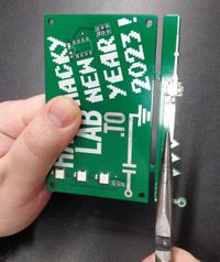
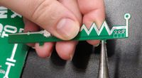
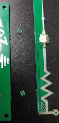
Using your hands and a pliers, twist the PCB to break away the mouse-bites connecting the 'CN-Tower-Resistor' PCB and Main PCB. | |||
[[File:Hny23-assembly-pcb-seperation-01.jpg|200px]] | |||
[[File:Hny23-assembly-pcb-seperation-02.jpg|200px]] | |||
[[File:Hny23-assembly-pcb-seperation-03.jpg|200px]] | |||
=== Solder right angle header to 'CN-Tower-Resistor' PCB === | |||
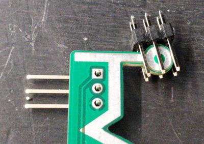
Solder the Right Angle Header to the 'CN-Tower-Resistor' PCB. | |||
* Make sure the plastic is on the side of the PCB with the white outline. | |||
* The 3x2 programming header can be used to support the PCB while soldering right angle header. This allows it to lay flat on a work surface and not tip over when applying the solder. | |||
[[File:Hny23-assembly-right-angle-placement.jpg|400px]] | |||
[[File:Hny23-assembly-right-angle-soldering.jpg|400px]] | |||
=== Solder down ATTiny25 micro controller. === | |||
This should already be taped down to your PCB panel in the correct orientation, but verify the chip orientation matches that of the silkscreen. | This should already be taped down to your PCB panel in the correct orientation, but verify the chip orientation matches that of the silkscreen. | ||
=== Solder programming header to Main PCB (Optional) === | |||
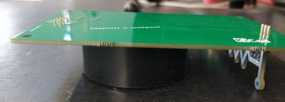
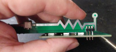
=== Solder'CN-Tower-Resistor' PCB perpendicular to Main PCB === | |||
* A roll of Electrical Tape is about the correct height to aid in this next step. | |||
* Place the Main PCB atop the electrical tape, with the 'CN-Tower-Resistor' PCB inserted below and supported by the work surface. | |||
* '''Solder only the First pin right angle header!''' (the one closest to the viewer in the photo | |||
[[File:Hny23-assembly-tower-soldering-jig.jpg|400px]] | |||
* Pickup the whole assemble, and while reheating the solder joint of the first pin, adjusting the positioning of the 'CN-Tower-Resistor' PCB to be perpendicular over the LEDs on the Main PCB. | |||
[[File:Hny23-assembly-tower-soldering-adjustment.jpg|400px]] | |||
* Solder the remaining pins on the right angle header. | |||
= FAQ = | = FAQ = | ||
;'''Q:''' How do we power the Plaque? | ;'''Q:''' How do we power the Plaque? | ||
:'''A:''' Provide regulate 5V programming header, either via the pin header if installed, or soldered directly to the vias if you choose to leave it off. Since ever hacker space is a bit different we left it as an exercise to those spaces. | :'''A:''' Provide regulate 5V to labelled points on the programming header, either via the pin header if installed, or soldered directly to the vias if you choose to leave it off. Since ever hacker space is a bit different we left it as an exercise to those spaces. | ||
= Design & Credits = | = Design & Credits = | ||
| Line 42: | Line 71: | ||
= Trivia = | = Trivia = | ||
= List of Hackspaces include in this Year's mailout. = | = List of Hackspaces include in this Year's mailout. = | ||
Revision as of 18:16, 8 January 2023
Hacky New Years 2023 Plaque
Assembly Instructions
Included Parts
- 1x PCB Panel
- 1x 3x2 0.1" Pin Header
- 1x 3x1 0.1" Right Angle Pin Header
- 1x ATTINY25 MCU (pre-programed)
Through Hole Soldering
All surface mount components come presoldered to the PCB. Through hole soldering is required to complete assembly.
Separate 'CN-Tower-Resistor' PCB and Main PCB
Using your hands and a pliers, twist the PCB to break away the mouse-bites connecting the 'CN-Tower-Resistor' PCB and Main PCB.
Solder right angle header to 'CN-Tower-Resistor' PCB
Solder the Right Angle Header to the 'CN-Tower-Resistor' PCB.
- Make sure the plastic is on the side of the PCB with the white outline.
- The 3x2 programming header can be used to support the PCB while soldering right angle header. This allows it to lay flat on a work surface and not tip over when applying the solder.
Solder down ATTiny25 micro controller.
This should already be taped down to your PCB panel in the correct orientation, but verify the chip orientation matches that of the silkscreen.
Solder programming header to Main PCB (Optional)
Solder'CN-Tower-Resistor' PCB perpendicular to Main PCB
- A roll of Electrical Tape is about the correct height to aid in this next step.
- Place the Main PCB atop the electrical tape, with the 'CN-Tower-Resistor' PCB inserted below and supported by the work surface.
- Solder only the First pin right angle header! (the one closest to the viewer in the photo
- Pickup the whole assemble, and while reheating the solder joint of the first pin, adjusting the positioning of the 'CN-Tower-Resistor' PCB to be perpendicular over the LEDs on the Main PCB.
- Solder the remaining pins on the right angle header.
FAQ
- Q: How do we power the Plaque?
- A: Provide regulate 5V to labelled points on the programming header, either via the pin header if installed, or soldered directly to the vias if you choose to leave it off. Since ever hacker space is a bit different we left it as an exercise to those spaces.
Design & Credits
- Matt Woodruff - PCB Design, PCB Population, ATTiny Programming
- Trent Drake - Graphics & Board Outlines
- Scott Sullivan - Project Catalyst, Documentation, Kit Assembly, Shipping
- Troy Denton - Circuit / PCB Design Review
- Vincent Marino - ATTiny LED Library Research
With thanks to Gary and other Hacklab members whom provided input during the design process.


