Laser Manual

History
You can find the history of the laser project on Andrew Kilpatrick's site.
Capabilities
Our laser is controlled by a Linux package called LinuxCNC. To drive the laser, LinuxCNC plays G-code files. G-code is not very standardized, so you should read up on the specific variety of g-code used by EMC2.
The position of the laser is controlled by the X and Y axes, and the height of the table is the W axis. Motion on all axes is made of discreet steps and can be reproduced extremely accurately. The X and Y axes move 1000 steps per inch and the W axis moves 4000 steps per inch.
The actual laser beam can be set to 15 different power levels using the switches on the panel. The max power rating is 25 Watts, and as of mid 2013 it has been measured at approximately this by Canadian Avenger. The power level can also be more finely controlled with G-code. To get a sharp line/cut, the laser needs to be focused. This is done by adjusting the W axis (the table) until the surface of your workpiece is exactly 2 inches from the lower surface of the lens. There is a white plastic post that can be used to measure this. From the base of the large end of the post to the top of the tapered part is 2 inches.
Size/Dimensions
- Max workpiece size: 24" x 18"
- Max laser cut area: 23.5" x 18"
- Bed vertical travel: 8" (no end stops! be careful not to drive it into the ends of travel!)
General Workflow Overview
- Obtain/create source work (either raster or vector).
- Convert source work to g-code which the laser understands. Inkscape provides an easy way to get started.
- If raster image (any major format) use the graster workflow.
- If SVG use SVGtoGCODE workflow.
- If DXF use dxg2gcode workflow.
- If TrueType font/text use TrueType Tracer workflow (then DXF workflow if outputting DXF)
- If other, find/create tools to convert source work to g-code.
- Load g-code into AXIS on the laser controller PC.
- Place workpiece into laser.
- Set beam power to OFF using override switch.
- Power ON laser control panel. The 'AMP ENABLE' and 'LASER ON' LEDs will blink once and turn off.
- Toggle machine power in AXIS to ON. The 'AMP ENABLE' LED should come on.
- Home all axes.
- Focus laser to proper workpiece height (using white focus aid peg as a reference) using manual control of the W axis.
- Ready laser power control system by rotating control knob on the grey panel to READY.
- Activate blower and laser tube by pressing and holding START on the grey panel until the blower starts.
- Check the Feed Override slider to make sure the job will run at the speed you desire.
- Set desired laser power and disable beam override.
- Start job in AXIS, keeping an eye on the work and being ready to hit the E-STOP switch if anything goes amiss.
- When job completes, set beam override back to ON and power OFF laser control panel.
- If you're done for the day, switch the control knob to STANDBY. If you're planning to laser more, just hit the STOP button. Either way will shut the tube off but leave the blower running until the fumes are all exhausted.
- Remove workpiece and marvel at how well the lazzor worked!
Precautions
- Always ensure the blower is running while the beam is on, no matter what material you are working with. Any kind of smoke can damage the lens, so the laser chamber has to be ventilated. The laser power control system should ensure this is the case by shutting everything down if the blower is not running, but it's a good thing to keep in mind anyways.
- Make sure the LASER TUBE is OFF (green TUBE light on the power controller is not lit) before opening the cover of the laser. There are interlocks for basic safety but this will protect your eyes absolutely.
- Do not leave the room while the LASER TUBE is ON. ESPECIALLY when working with flammable materials.
- Use only known materials in the laser. If you want to try a new material, do some research and careful experiments first. Certain things have been known to explode or release poison gas under the laser. Check out our Materials Reference.
- Test your jobs first with the beam power off. Watch the red "Laser On" LED to make sure it's doing the right thing.
- Do not eat anything that has been lasered.
- Do not laser your body.
- Wear safety goggles if you are running the laser with the cover open, for some reason. But don't do this.
- You don't need safety goggles when using the laser normally.
Techniques
HowTo: Load your image for laser cutting
To send your gcode (cut) or png (etch-and-cut) image to the linux machine that runs the laser:
- scp your image to your account on shell.hacklab.to. This puts your image somewhere the laser can get at it.
- On Windows, the best program for this is WinSCP. You can get it here: http://winscp.net/eng/index.php)
- On linux, run this (eg) from the command line:
scp supernerd@shell.hacklab.to :thisismyimage.png
- At the laser machine, open a terminal.
- Navigate to the graster directory, and run graster on the image. Graster will generate both a cut job and an etch job from the image.
Converting Files
There are generally two kinds of jobs you can do with the laser: raster and vector.
A raster job fills in a solid shape by moving the laser back and forth and etching each horizontal line of the shape. If you want to draw an image on something, this is generally the way to do it.
With a vector job, the laser moves along an arbitrary path. This is mostly for cutting, but if you just want to draw razor thin lines, you can use vectors for that too.
Graster Conversion Workflow
To create raster jobs, use Graster: http://github.com/jedediah/graster
Warning: you cannot use the "touch off" feature of EMC with a Graster job, it will not work and bad stuff will probably happen. Before starting a job, make sure the coordinate system is reset by going to Machine -> Zero Coordinate System -> P1 (the first option).
Graster is already installed on the laser PC you should use it there, if possible, because it is still a bit tricky to install.
To use it:
- Load the image onto the laser printer.
scp image.png hacklab@laser.hacklab.to/image.png
- SSH into the laser printer.
- Run the script on your image.
../graster/graster.rb image.png
- The output results in three files:
image.png.cut.ngc - A box cutout of the image.
image.png.raster.gmask - The gmask file with laser instructions.
image.png.raster.ngc - This is the main Gcode file that you want to load into the cutter.
Advanced Graster info
To run Graster yourself, you will need Ruby 1.9, not Ruby 1.8. At present, the version of 1.9 in the Debian/Ubuntu repository is very old, do not install it. You will have to build Ruby 1.9 (or later) from source (http://www.ruby-lang.org/en/downloads/). You will also need to install RubyGems and a gem called rmagick (which is used to read image files). This is all a bit of a hassle and a simpler install method is planned for The Future.
Run graster.rb for detailed usage instructions.
The image can be any common format.. PNG is probably best. A job can be configured with command line options or a configuration file. You can generate a default config file with the -g option. A config file looks like this:
dpi: [500, 500]
on_range: [0.0, 0.5]
overshoot: 0.5
offset: [1.0, 1.0]
repeat: [1, 1]
tile_size: [3, 1]
tile_spacing: [0.125, 0.125]
feed: 120
cut_feed: 20
corner_radius: 0.125
dpi: The resolution you want to draw the image at, in dots-per-inch. The laser's natural resolution is 500x500 so you should probably use that for best results. This means that 500 pixels in your image will be one inch on the laser. If you want it bigger, you should scale up the image in an image editing program that has good filtering or better yet, get a higher quality source image.
on_range: The range of lightness values for which the laser will be on. Images are converted to greyscale with range 0..1 and tested against this range. Since the laser tends to darken things, the default is to laser dark pixels.
overshoot: The stepper motors that move the laser can't start and stop instantly, they need time accelerate and decelerate. When drawing raster lines, you want to the laser to be moving at a constant speed from one end all the way to the other. We overshoot the end of the image so the X axis motor can change direction without affecting the burn. The default value seems to be enough for even the fastest speed.
offset: The location of the bottom left corner of the image, relative to the bottom left corner of the laser table. This allows you to reposition the whole image. EMC has a similar feature in AXIS but you can't use that feature with Graster.
repeat: Number of times to repeat the image in the X and Y directions. Yup, this lets you burn a whole batch of things instead of just one.
TODO:
tile_size: Size of repeated images
tile_spacing: Gap between repeated images
feed: Feed rate for rastering
cut_feed: Feed rate for cutout
corner_radius: Corner radius of cutout, 0 for pointy corners
Graster Job Output/Running
Graster output consists of a cut G-code file (filename.cut.ngc), a raster G-code file (filename.raster.ngc) and a mask file (filename.raster.gmask).
- The cut file is a simple g-code sequence that just cuts out the outer perimeter rectangle of the image/job.
- The raster g-code file consists of a constant raster pattern covering the entire surface of the piece. It's normal for this to appear as a solid white box when loaded into AXIS (if you zoom in you will see the constant pattern).
- Once the raster job starts in AXIS, it executes the 'M101' g-code command, which is set up to launch the Graster Streamer. The g-code itself just tells the laser head to move back and forth over and over, and the Graster Streamer actually streams the bitmap data to it (via the mask file).
DXF Conversion Workflow
- I have had success doing 2D designs in QCad which is free for Linux and has ready-to-run packages in Ubuntu. It is installed on pubtoob at the lab. QCad saves very clean DXF files.
- I have used this python dxf2gcode converter. It's pretty rough feeling, but if you set it up properly you can make gcode that works on the laser. Sometimes it has trouble with curves and makes invalid gcode, but it's open source so you can fix it!
- I have found that DXF files from CAD programs other than QCad cause the dxf2gcode converter to break. Your mileage may vary!
dxf2gcode configuration
- dxf2gcode_v01_config.cfg
[Paths]
save_path = .
load_path = .

[Depth Coordinates]
axis3_retract = 0.01
axis3_slice_depth = -0.01
axis3_safe_margin = 0.01
axis3_mill_depth = -0.01

[Axis letters]
ax2_letter = Y
ax1_letter = X
ax3_letter = Z

[Plane Coordinates]
axis1_start_end = 0
axis2_start_end = 0

[Feed Rates]
f_g1_plane = 10
f_g1_depth = 200

[Route Optimisation]
mutation rate = 0.95
max. population = 20
max. iterations = 300
begin art = heurestic

[Import Parameters]
point_tolerance = 0.01
fitting_tolerance = 0.01

[Tool Parameters]
diameter = 0.1
start_radius = 0.2

[Debug]
global_debug_level = 0
- dxf2gcode_v01_postprocessor.cfg
[Number format]
post_decimals = 4
pre_decimal_zero_padding = 0
signed_values = 0
pre_decimals = 4
decimal_seperator = .
post_decimal_zero_padding = 1

[Program]
cutter_comp_left = G41%nl
feed_change = F%feed%nl
cutter_comp_off = G40%nl
rap_pos_plane = G0 X%X Y%Y%nl
lin_mov_depth = G1 Z%Z%nl
tool_change = T%tool_nr M6%nl S%speed M3%nl
rap_pos_depth = G0 Z%Z %nl
cutter_comp_right = G42%nl
lin_mov_plane = G1 X%X Y%Y%nl
arc_int_ccw = G3 X%X Y%Y I%I J%J%nl
arc_int_cw = G2 X%X Y%Y I%I J%J%nl

[Line numbers]
use_line_nrs = 0
line_nrs_step = 10
line_nrs_begin = 10

[General]
write_to_stdout = 0
code_end = M63 P0 (laser off)
	M5 (Spindle off)
	M2 (Prgram end)
code_begin = G20 (Unit in inch)
	M63 P0             (start with laser off)
	G0 Z0.002          (ditto)
	G0 X2.5 Y3         (move to start position)
	M3 S1              (enable laser and set to full power)
abs_export = 1
SVG Conversion Workflow
- Av developed an SVG to GCode converter. It natively runs in Windows and runs in macOS/Mac OS X (standalone emulator) and Linux (via Wine) and is available here: https://github.com/avwuff/SVG-to-GCode
- the SVG converter works well with files from Inkscape which is free on many platforms and I think also installed on pubtoob.
TrueType Font Workflow
- The TrueType Tracer is an open-source tool that takes a truetype font and some desired text, and spits out either g-code or a DXF. This has been used to generate a DXF that was then loaded into CAM Expert to generate g-code, the direct g-code output from the tool hasn't been tried yet.
Fusion360 Workflow
See: https://github.com/IgorYeremin/fusion-postproc
Hardware Overview
Major Components
- Laser machine, the large grey box that is "the lazzor" itself.
- Laser tube/cooling system, behind main laser machine box.
- Laser control PC, on the platform to the right of the laser machine.
- Laser ventilation system, overhead behind the laser.
- Laser power control unit, the grey box under the laser control PC.
- Rotating red light, outside the laser room that indicates the laser is in use.
Control Panel
- Top row (left to right)
- Red LASER ON LED. This indicates that the laser beam will be ON, if the overrides further down the path are disabled. This LED is useful for checking jobs before turning the beam on for the first time.
- Yellow AMP ENABLED LED. This indicates that the laser control board is receiving a 'keepalive' signal from EMC2/AXIS, and the machine is 'powered on' from the PC's point of view. When flashing, the machine is stopped due to an emergency stop signal or open interlock switch.
- E-STOP (emergency stop) toggle switch. When in the down/OFF position, the machine operate normally. When toggled up/ON, the machine and EMC2/AXIS are put into emergency stop mode, all movement is stopped, and the laser beam is turned off.
- Bottom row (left to right)
- Four LASER PWR (laser beam power level) toggle switches. These control the actual beam output power, in binary. Add up the numbers of all switches that are up/ON in order to get the output power level selected.
- Beam override toggle switch (labeled OFF). When in the UP position the beam power is turned off, overriding the beam power level selected with the other four switches. When in the DOWN position, the beam is allowed to be turned on.
- CONTROL PWR toggle switch. This turns on the machine's control circuitry.
Power Controller

- Top row (left to right)
- Master controller - Set to STANDBY to put system into standby when it is not being used, READY to use the laser, or BLOWER ONLY to just run the blower to ventilate the space without lasering.
- START - Press and hold for ~0.5 seconds to start the system, once the master controller is set to READY.
- STOP - Press to shut the tube off and start the post-shutdown ventilation cycle.
- E-STOP - Press to immediately shut the tube and blower off, and signal the motion control system to stop moving the laser.
- Middle row (left to right)
- BLOWER Light - Flashes when the blower is coming up to speed and being checked, stays on while the blower is running.
- TUBE Light - Flashes when the tube is coming on and the cooling is coming up to speed, stays on while the laser tube is powered.
- FAULT Light - Comes on when there is a serious fault with the system, such as the blower not running or not generating appropriate pressure in the ducts.
- FAULT Buzzer - Buzzes when there is a fault.
- Bottom
- PLC - Controls power to the laser tube, blower, and light outside the room, and monitors pressure in the ducts.
Further details here: Laser Power Controller
Electronics
Details on laser internal schematics and code documented here: Laser_Electronics
EMC2
Homing
EMC 2.3 requires all axes to be homed before running any program. If you don't see little crosshairs next to the coordinates of all 4 axes, just click "Home all". If, for some reason, the gantry gets moved while AXIS is running, you need to "Home all" again because EMC2 has no way of knowing that the carriage is not in the position it thinks it's in.
Focussing
To get the tightest beam, the bottom of the lens should be exactly two inches from the surface of the workpiece. If it's closer or further, you will get less power and more charring around the beam's path.
The focus is adjusted with the W axis in EMC, which controls the table height. Use the + and - buttons to manually move the table. The + moves the table up (so the lens 'moves down' in relation to it), and - moves the table down (so the lens 'moves up' in relation to it). For fine adjustments, change the increments from "continuous" to some small amount. 0.005 inches should be precise enough.
There is a small white plastic post near the laser that can be used to measure the height. Place the fat end on the surface of your workpiece and the flat part of the notch against the side of the lens. If the post doesn't reach the lens or the lens is below the notch, make a coarse adjustment as necessary. Be careful not to bring the lens down on top of the post. When the lens is in the notch, raise the table in small steps while looking straight down at the post through the window. As soon as it moves away from the lens, back up one step. For cutting through thicker material, you want the laser's focus point to be 'inside' the material, so once you have the focus dialed in using the post, move the table up by half the thickness of the material.
G-code
How Our Laser Uses G-code
X axis: gantry right/left, 500 dpi
Y axis: gantry far/near, 500 dpi
W axis: table up/down, 2000 dpi
The laser is wired to spindle on/off (M3/M5) and either of the following:
move Z axis to -0.002/+0.002 (on/off respectively)
or
use "digital out" commands "M62 P0" / "M63 P0" for on/off, respectively
That is to say, the laser is on if and only if the spindle is on and one or both of the Z axis and digital out are on.
Controlling the laser with the Z axis can be tricky because EMC2 thinks that there is a moving physical object attached to the axis and tries to constrain its motion. The M62/M63 commands are realtime and instantaneous, meaning that they can be used to turn the laser on/off without affecting X/Y motion, at least in theory. You can put these commands on the same line as a motion command, in which case the laser will be turned on/off at the *beginning* of the motion.
The following feature still needs a bit of tweaking. Don't use it for anything serious yet: The power of the laser can be controlled from G-code by setting the spindle speed with S#, where the number is between 0 and 1. This will effectively be multiplied by the power level set with the hardware switches. Power level set with the S command is fairly detailed, with at least 50 distinguishable levels. The power can be set so low that it only leaves a faint mark on paper.
A G-code program for our laser should look something like this:
M63 P0             (start with laser off)
G0 Z0.002          (ditto)
G0 X2.5 Y3         (move to start position)
F60                (set feed rate)
M3 S1              (enable laser and set to full power)
G1 X7.5 Y3 M62 P0  (turn laser on and start controlled movement)
...
G0 X0 Y17.5 M63 P0 (turn laser off and move gantry out of the way)
M5                 (disable laser)
M2                 (end program)
Since EMC2 automatically turns off the spindle when a program stops, there should be no danger of the laser ever being on unexpectedly. However, just to be safe, you should turn off all laser related signals at the beginning and end of every program.
Troubleshooting
Beam does not turn on/stays on all the time during Graster job
- Ensure the coordinate system is reset by going to Machine -> Zero Coordinate System -> P1. You can't use the "touch off" feature of AXIS with Graster.
Gantry moves as desired, but no beam is output
- Check to ensure the beam override switch is not on.
- Check to ensure that a non-zero power level has been selected.
- Switch Axis to show "Machine Coordinate View" and make sure the Z axis is touched off at the machine's zero point. if Z is touched off high or low, the laser control could be erratic.
- Switch to the MDI [F5] tab and enter the following commands in the MDI Command window, clicking "Go" after each: M3, S1
- Run the sed command at the bottom of this wiki page (includes the M3 S1 from above)
- Check to make sure the red light outside the laser room is on and spinning. If it is not, speak to someone who has previous laser experience.
Aborting a test/job
- If streaming a graster job, the easiest way to abort the job, without having to kill processes manually, is to hit the big ESTOP switch
Ventilation system makes a soft buzzing and the lights dim when turned on, air is not moved
- This happened on March 28, 2010, and again in early 2013.
- Ensure the motor is unplugged before performing any further troubleshooting!
- Untape the side of the ventilation motor 'can' closest to the wall, and bend the metal back some so you can see the pulley on the motor and the belt that drives the blower.
- Spin the blower by hand (push/pull the belt along). If it does not spin freely, investigate why.
- Ensure nothing (metal, loose tape) is interfering with the belt, ensure nobody has anything that will get caught in the belt/blower/motor, and plug in the ventilation system. This manual manipulation resolved the issue the previous time it happened.
- If this resolved the issue, put the ventilation system back together, taping up any openings that might let air in/out in the wrong place.
- If this did not resolve the issue, troubleshoot further.
- Mail the members list to let everyone know it happened again, so we can troubleshoot what might be happening and try to resolve it.
Gantry moves much faster or slower than expected
- Check the 'Feed Override' slider at the left side of the screen to ensure it is set at 100%.
- Check to make sure your F command is correct and appropriate to the specified coordinate system.
FAULT light and buzzer are on
- Error code will be displayed on the PLC display.
- DUCT UNDERPRESS - The duct pressure is too low. Likely the blower is not running or the window has been closed, check these things and resolve the issue.
- DUCT OVERPRESS - The pressure in the duct is too high. Check for clogs in the duct.
- BATT LOW - The backup battery in the PLC is low. Replace it or contact the operations team to do so.
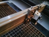
Mirror misalignment (double laser beam or only cutting on one side of bed)
- The first mirror (on the left of X carriage) has been going out of alignment recently for unknown reasons
- This causes the laser to hit the second mirror (on head) off-centre
- Get help from someone who has fixed this before!
- Paper masking tape and firing laser on the minimum power level for a second can be used to see where the beam actually hits
- Realignment procedure
- Parts diagram:
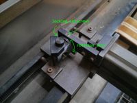
- Loosen the two locking setscrews
- Rotate mirror a fraction of a degree
- Check alignment by firing at tape
- Repeat until laser hits the same spot on the opening for the second mirror when the head is at leftmost and rightmost positions along the slide
- Slowly snug setscrews to fix position
- Re-check alignment
- Repeat whole process if needed


Materials Reference Tables
The laser cutting area is 23.5" x 18" (596.9mm x 457.2mm).
Materials
Suggested feed rates and power levels are a starting point. Experiment! Test before you start your job.
| Material | Aliases | Outcome | Recommendation | Maximum Thickness Cut | Suggested Feed Rate (in/min) and Power Level |
|---|---|---|---|---|---|
| Acrylic | PMMA, Plexiglas, Perspex, Lucite | Very good results from light etching to cutting with minmal smoke | Great to use in laser. | 6mm or almost 1/4" | F4-F20, depending on thickness and colour. Full power for cut. Etch at 2 power. |
| Acrylic - 0.020" to 0.060" | n/a | Works great for stencils | Available at Gwartzman's (20" x 16") | All | Full Power - 0.030" ~35ipm |
| Cardboard | None | Faint-to-medium discoloration to cutting with minimal smoke | Good for initial test runs of jobs. Use a high feed rate to avoid burning. | N/A | F50-F100, Power 8. |
| Black bristol board | None | Clean cut with minimal smoke and no burning whatsoever | Recommended for making spray paint stencils | N/A | F20 at 329in/min, power 3-4 |
| Polycarbonate | Lexan, Makrolon | Smoke and flame | Bad for lasering, creates highly toxic fumes and messy ash. | ? | |
| Anodized Alumnium | Surface etching | Anodized aluminum can be marked (but not cut) | N/A | Full power @ 300in/min | |
| Bare Steel | No effect | Our laser can't touch it | n/a | ||
| Painted/Powder Coated Metals | PC Cases | Paint removed, shiny surface revealed | Use very high power setting, and clean work with soap and water after cutting. Be weary of toxic fumes from burning paint. | n/a | 20-50, Full Power |
| Clear Glass | Cutting/Etching | Our laser can easily mark glass. The glass will often crack or shatter due to thermal shock. Cutting may be possible. | ? | ? | |
| PVC / Vinyl | AVOID | Releases toxic chlorine gas. Do not laser! | n/a | ||
| High-density polyethylene | HDPE | Barely cuts, melts badly, makes a mess. | n/a | ||
| Wood | Cuts or Etches | Wood etches very nicely. Play with speed/power settings to minimize charring. Thin woods (veneer) cut nicely at high speed. Cover with painters tape before lasering to reduce cleanup from smoke staining wood adjacent to cuts. | >0.5mm (20 thou) | F20, Power 8 | |
| Plywood, Wood composites, MDF | Toxicity unknown. Probably bad. | ? | |||
| T-shirt, 100% cotton | Awesome! | shirt needs to be wetted in order not to burn / curl. Use metal between front and back. | ? | F200, power 6 | |
| overhead transparency | polyester | works well | super useful for things like solder paste masks | ? | ? |
| Slate tile | Stone | Surface alteration | Possible to etch at low speeds, but creates ugly white ash. High speeds create a sand-like appearance that is rigid and looks nice. Downside: surface finish varies strongly with focus; requires a very flat and level surface. | N/A | 200% speed, Full power |
| Reynolds Freezer Paper | Cut | Cuts cleanly, great for making stencils that can be ironed onto t-shirts then cleanly removed. Make sure you laser it with the plastic side down for both curvature reasons and so you can iron it on when you're done! | N/A | 250 in/min, power 4 |
Power Level Results
| Material | Power Level | Movement Speed | Result |
|---|---|---|---|
| Thin Brown Cardboard | 1 | 300in/min | Medium-faint darkening of material (minimal difference to surface texture) |
| Thin Brown Cardboard | 3 | 300in/min | Medium cut (not all the way through) |
| Black bristol board | 3-4 | 329in/min, F20 | Near full to full cut, very low flameout (if any). Perfect clean cut with minimal charring or risk of burning |
| Acrylic, 6mm | 15 | 4in/min | Complete cut, slight bevel and kerf to cut. Best result if laser focus point is 'inside' the material |
| Acrylic, 1/8" | 15 | 20in/min | Almost complete cut, full cut likely at 10in/min |
| Acrylic, 3mm | 15 | 70% of 400 feed speed | clean cut, and the tool width is 0.2mm per cut, so a box 0.4mm larger both x and y fits upside down (but not rightside up, due to angle of the cut) |
Tips
Cutting Thick Acrylic (Sarahemm)
I've found this method results in a nice reliable cut with less acrylic vapors redepositing on the work, and less chance of things flaming up. This also gets around the issue where thick material melts during the cut and re-solidifies behind the cutting beam, as the second pass gets through this melted material.
- Run a first pass at normal speed, at 3/4 of the power you would use to cut all the way through
- Run a second pass at 150% speed, at 1/2 of the power you would use to cut all the way through
Counterbores (Sarahemm)
Counterbores can be done on the laser if you're using acrylic. Cut the hole as you normally would, then add concentric circles around it every 0.25mm or so from the hole to the outer diameter of the counterbore you want. Run the laser at relatively high speed and low power, repeating these concentric circles over and over until you're down to the depth you want. If you use too high a power or too low a speed (so as to try to do it in one pass, for example) you end up with a lot of melted acrylic goop and don't get a useful counterbore. Repeated lower power passes vaporize the acrylic and it works much better.
Removing Redeposited Acrylic "Fog"
When etching (or cutting, but most noticable when etching), the vaporized acrylic can sometimes deposit back on the surface of your work, resulting in a "fog" over it that doesn't look nice. Buffing the surface with a Mr. Clean Magic Eraser takes this off cleanly without scratching the surface of the acrylic at all. There's one kept in the cupboard with the acrylic (looks like a white sponge).
Inkscape Example (a good way to get started)
One of the easiest ways to get started with the laser cutter is via a program called Inkscape. Once you create a drawing in Inkscape it's relatively easy to transform it (with the help of the Gcodetools plugin/extension) so that it can be cut with the laser. Here's the steps for doing that (more details needed):
1) Start by installing Inkscape as well as the Gcodetools extension for it. (Note: If you want to skip this step and get started right away, you might want to pull out Hacklab's Dell Laptop since it already has a ready-to-go version of Inkscape installed on it. The power adaptor for the Dell Laptop is in the bin marked "power adaptors" in the bins closet). Here's the steps for installing Inkscape and the extensions you'll need (Note: need more detail here):
- Inkscape can be downloaded from Inkscape.org
- Install Inkscape's Gcodetools extension (Download from github gcodetools now! more information on that: here, and here. download tar.gz here
2) Next, create your drawing in Inkscape:
- To make your life easier, you should select File/Document Properties/ and then under the "Page" tab you should change "Default units to "mm" from "px" so that you know exactly how big your drawing will be when it's cut out.
- Go ahead and make your drawing
- Ensure that all objects are paths. To do this, first, make sure all items in your selection are ungrouped (Shift+Ctrl+G). Next, convert all selected objects to paths (Shift+Ctrl+C).
- Make sure you consider the point of origin for your drawing (default of 0,0 in the bottom left corner of the page). When you start cutting on the laser you'll need to align this origin to the corner of your work material. So to avoid wasted material, try to squeeze your drawing as close as you can to the bottom left corner of the page. (Note: is there any way to change to point of origin on your inkscape drawing?)
3) Ensure your settings are correct for the Gcodetools extension (Extensions/Gcodetools/All in one...) The following screenshots depict sample settings that you can use:


4) Then, once you have the above settings configured the way you want, turn your drawing into g-code that's suitable for the laser cutter.
- Once you've opened Extensions/Gcodetools/All in one...Start by going to to the "Preferences" tab to ensure you have the file and directory settings you want for your g-code file
- Next, select the "orientation" tab and then hit the "apply" button
- Then go to the "tools" and then hit the "apply" button
- Last click on the "path to g-code" tab (then hit "apply") (note: you may get a "no paths are selected" error, just click "ok" to work on all available paths).
- ...you should now have your g-code generated file. You can find it in the default directory (open the Gcodetools extension, and click on the "Preferences" tab to see what your default directory is)
5) Sometimes your g-code file will still have problems with it. For example, you might do a dry run on the lasercutter and find that the "laser" LED light indicator is not turning on. So you might need to do a find and replace sequence on your g-code file to fix it up. If you're command line savvy, then just apply the following to fix your file:
cat myfile.gcode | sed -e 's/M3/M3 S1 F500/' -e 's/^G00 Z0.010000/M63 P0/' -e 's/^G01 Z-0.010000 F.*/M62 P0/' -e 's/\( Z-0.010000[0-9]*\)\( .*$\)/\2 M62 P0/' > myfile_fixed.gcode
6) Bring your file to the laser cutter. You can either move it over manually on a USB stick or send it over electronically.
- First, login to the laser's computer (hint: it's the same password as a lot of other things in the lab)
- Open EMC2 if it isn't already opened and running.
- You now have two main options for accessing your file, either USB stick or upload via the network:
- For USB stick, you'll probably want to try finding your USB stick under "media" in the top level folder. I found mine in /media/disk/ (your mileage may vary)
- For uploading via the network instead, you will want to use the address: 192.168.111.186
- Note, to locate your gcode file you'll want to make sure you have selected the "show all files" option when browsing around
- For USB stick, you'll probably want to try finding your USB stick under "media" in the top level folder. I found mine in /media/disk/ (your mileage may vary)
7) Now you should be ready to use your file to begin cutting on the laser. For that part, go ahead and follow these steps.
Gallery
Coming soon?